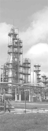
Tanks and columns
Welded steel tanks
Introduction
The catalogue presents information including the name and place of application of a welded steel unit, a drawing with general dimensions, and dimensions for connection and assembly purposes.
The units listed in the catalogue are not designed for:
- use as an underground tank;
- transportation of operating media (in mobile installations);
- lining, gluing and application of coatings, except paint-coating
All units have dimensions suitable for the use in railway transport in CIS (Commonwealth of Independent States) countries and are approved by the Ministry of Transport of the Russian Federation.
General information
Technical requirements for the materials, manufacture, acceptance and testing methods, and conservation of products are based on the OST 26-291 and GOST2630 standards.
The products listed in the catalogue are made with or without heat treatment.
Design modifications (position of sockets and couplings etc.) are acceptable if properly indicated in the questionnaire.
Operational modifications to accommodate differing operating conditions (temperature, corrosive factors, etc.) and changes concerning sealing materials, fittings, M&C instrumentation etc. will follow the documentation of the project in which the device is to be incorporated.
Application specifications should take into account the following:
- The device is operable with a working medium which must not exceed a certain maximum admissible density, and the weight of the device in an operating mode must conform to the admissible values specified in the relevant Table in the catalogue.
- The admissible value of external pressure acting on the device at the design density of the working medium is 1600 kg/m. If any density and pressure differences are foreseen, they must be specified by the engineering organisation responsible for the project in which the device is to be used.
- The products in the catalogue, except flat bottom vertical devices, may be operated with any working medium; flat bottom vertical devices may be operated with media (substances) designated as NG, TG, GV, GZ (GOST 12.1.004), and categorised in safety class 3 or 4 (according to GOST 12.1.007.
- Where a device is to be used in a site with a seismic activity magnitude of 7 or more, the engineering organisation responsible for the project in which the device is to be used must indicate this, or state that the relevant calculations are not required. The seismic activity calculations must be made with due regard to the specific intended operating conditions of the device. Where relevant, seismic activity related calculations will be based on GOST 24756 or SNiP II-7-81.Where calculation results allow the operation of the device in a site with a seismic activity magnitude of 7 or more, or where it is reasonably determined that the calculation is not required, the following indication should be made in Column 12 of the questionnaire: “Operability confirmed”.
- Conical flange bottom units may be used in technically substantiated cases (elliptical bottom units are to be used in all other cases).
Any use of the products in operating conditions differing from those foreseen in design calculations are subject to approval by the engineering organisation responsible for the project in which the device is to be incorporated on the basis of the sources provided in the catalogue. In such case, the following indication should be made in the relevant fields (where the values are exceeded) of the questionnaire: “Operability confirmed”.
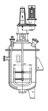
Vertical steel units with agitators
Vertical steel units with agitators designed for various single-stage and multi-stage processes involving liquid media, with dynamic viscosity of 50 Pz (5 Pa) and density of 2,000 kg/m.
The operating medium contained within a unit may be a neutral liquid, or an aggressive, extinguishing or toxic liquid, emulsion, liquefied gas or suspension with a concentration up to max. 30%.
The jacket and the coil contain pipe water or cycled water, mixture, condensate, saturated steam or a heat transfer fluid; temperatures may range between -30° C and + 250°C, or even above.
The selection of a suitable unit is based on calculations of the homogenisation, suspending, emulsification or heat transfer process, as applicable, and the control documentation RD 26-01-90-85, or on experimental model tests and analyses of the general transfer from a model device to a real device.
Device types, basic parameters and dimensions comply with GOST 20680.Agitator motor outputs and speeds are shown in Table 2.8. Applicable technical requirements for materials, manufacture, acceptance procedures, testing methods and conservation of products are as specified in OST 01.26.1244, GOST 52630.
The climatic class of devices is U2 as per GOST 15150, i.e. the devices are suitable for applications up to -30°C. If the ambient temperature drops below 0°C, measures must be taken to prevent the coolant in the shaft seal from freezing.
Based on customer’s requirements, as specified in the quotation letter, devices of climatic class T2 as per GOST 15150 may be supplied.
Devices may be installed in sites with Richter seismic activity magnitudes of max. 8, provided that the unit is anchored to a base plate. Steels from which the housings are made are listed in Table 2.2.
The manufacturer may decide to substitute a particular make of steel according to Table 2.2, subject to compliance with the valid technical documentation and standards.
The agitator, shafts and other parts that come in contact with the working fluid are made of stainless steel having the same properties as steel of which the housing is made.
Seamless welded jackets are made of carbon steel. The grade of steel is selected according to Table 2.2 and the requirements of OST26-291 and GOST 52630.
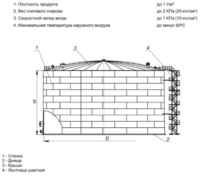
Oil, oil product and water storage tanks
Vertical steel tanks (VST) The tank housing has a conical shape: it is a cylindrical vessel made of welded sheets with a designated inner diameter and height. A tank is equipped with specific stairs and side walls that are appropriate to the given tank dimensions/size. The tank design follows roof-top tanks.
Tanks are intended for the storage of oil and oil products with densities of up to 1 t per m3, and of water.
The flat bottom of a tank is anchored to a base plate in the place of operation.
The tank top is conical and is made of sheets. A tank is equipped with an exterior stairway for operators. It also serves as a handling frame during transportation of the tank to the installation site.
The basic material is low-alloyed steel or carbon steel.
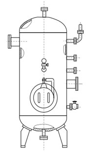
Air collectors/air tanks for stationary compressors
Air collectors are made with nominal volumes of
0,5; 1,0; 1,6; 2,0; 3,2; 4,0; 6,3; 8,0; 10; 16; 20; 25; 32; 40; 50 m3; and with operating pressures of 0.8; 1.0; 1.4MPa (8, 10, 14 kg/cm2). These products are designed to reduce pressure fluctuations in pipe systems and to hold an air reserve for the operation of stationary air compressors for general applications and rotary air compressors with operating pressures of up to 1.4 MPa (14 kg/cm2).
Air tanks may be used as receptacles and storage containers for nitrogen, argon and other inert gases.
Air collectors are designed for application in sites with seismic activity magnitudes of 7 or more as per a 12 point scale.
Subject to replacement of supporting legs with cylindrical supports and to a height not exceeding 10 m, air collectors are considered to be operable in sites with a seismic activity magnitude of up to 10; however, calculations of seismic effects on the strength are required in each case.
Climatic classes of air collectors:
- For applications in moderate and cold climates: UHL1 as per GOST 15150.
- For applications in tropical climates: T1 as per GOST 15150.
Air tanks may be used in low-cycle load applications with periodic increases and decreases in pressure. If a low-cycle load application is foreseen, this must be specified in the purchase order for an air tank.
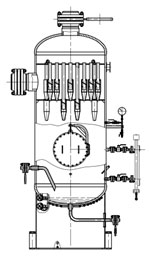
Liquid mesh filters for pipe systems
Liquid mesh filters for pipe systems
Mesh filters for liquids are designed for pipe systems with nominal pressures of 1.6 MPa and 4.0 MPa and for liquid temperatures ranging between -60°Сand +300°С.
Filters are intended as protection for pumps and other devices used within oil, chemical and gas process plants where the fluids processed contain solid mechanical intrusions not exceeding 200 μm in particle size.
The fluid safety classes are 1, 2, 3 and 4 as per GOST12.1.007-76.
The design, parameters and dimensions of filters conform to ATK 24.218.04-90, ГСТУ 3-17-207-2000.
Two filter design versions are available, differing in the way of connection to the pipe: version 1 uses flange connection and version two is welded.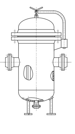
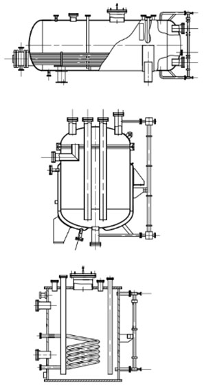
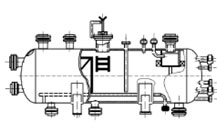
Oil and natural gas separators
Oil and natural gas separators are intended for degassing and purification of oil and gas at the initial, in-process and terminal stages of industrial plants, for the collection and preparation of output from oil deposits. The devices are designed for operation in mild and moderately cold climates with at the following operating air temperatures:
- For a mild climate: from +40°С to -40°С ;
- For a moderately cold climate: from +40°С to -60°С .
Oil and natural gas separators (NGS) are operable in areas with seismic activity magnitudes not exceeding 6.
Multi-cyclone separators
The devices are intended for the cleaning of gases by removal of condensed liquids and mechanical intrusions in gas treatment systems of compressor stations in underground gas storage sites. Separators are made in conformity with OST26 291-94 and GOST R 52630-2006.
The efficiency of gas cleaning from condensed liquids and mechanical intrusions with a particle size of 40 μm is min. 99.5%.
Nominal pressure in the device is 16 MPa.